It has been a fair while since I’ve dabbled in embedded programming but since joining the Bristol Hackspace and Bristol Communal Modular project, I have been keen to get back to it. Having recently built the Turing Machine and some of it’s expanders, at the Hackspace, we have had a need for a quantiser, since the Turing Machine is a bit too random for pitch CV. Great for sound design/techno kinda stuff but a bit too random for melodic music usually.
After a bit of searching around, I found the excellent open-source Sonic Potions Penrose Quantiser that is based around the ATmega168PA, which I have a few of laying around. Previously I had programmed the chip using assembler, which was quite challenging, so I was glad to see this project was written in C. First of all though, I’d need to get the basics sorted and figure out uploading to the microcontroller. I was keen to keep the programming hardware minimal and generic, so I wanted to program the chip via the TTL-232r-3v3 FTDI cable. This turned out to be more challenging than expected, drawing on lots of fragmented and in some cases misleading information scattered across the internet, so I’ll document the process here for future reference.
UART, ISPs and Bootloaders
There are two ways to program the microcontroller, we can either write the entire flash memory using an ISP or write a bootloader and then program the remainder of the flash memory using UART (ie. the FTDI cable). The gotcha here is that AVRs don’t come with a bootloader preinstalled out of the box so we need an ISP to initially program the bootloader then the chip can be programmed using UART from then onwards.
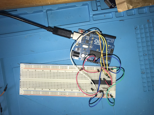
One way to program the bootloader is to use an Arduino. I have an Arduino Uno that I used. There are lots of tutorials out there for how to set this up but the most useful one I found is ElectroPeak’s guide.
As a basic summary, you need to:
- Upload the ArduinoISP sketch to the Arduino Uno.
- Set the circuit as above, in short connect the Arduino’s ISP pins to the equivalent pins on the breadboarded ATmega, use a 100nF (or higher) capacitor across the power lines and set up the 16MHz crystal with 2x 22pF caps to ground on each pin of the crystal.
- Add the target microcontroller profile to the Arduino IDE. This involves finding the correct repo for the microcontroller on this Github page (for ATmega168, it’s the MiniCore repo), adding the json URL to the Arduino IDE’s Board Manager URL’s section in Preferences then updating and installing the profiles using the Arduino IDE’s Board Manager. Follow the How To Install instructions on the Github page for more info.
- Once you have the profiles installed, select the correct target board in the Arduino IDE then burn the bootloader on the chip.
Programming the microcontroller
Once the bootloader is installed, it’s then possible to upload a compiled binary from the Arduino IDE (or using avrdude directly) on to the chip using a UART programmer, such as the TTL-232r-3v3 FTDI cable. Initially, I ran through the process using the Arduino Uno’s built in UART programmer and the process for that is described in detail on the ElectroPeak guide.
However, my goal was to make use of the FTDI cable as that seemed the cleanest solution. First of all, we need to get Arduino to recognise the FTDI cable under Tools > Ports in the Arduino IDE. I am using a Mac and there seems to be a driver ready to go as soon as I plugged the device in. However, I’d seen some reports that suggest that the stock driver may not fully support the device and that it is better to install the drivers directly from ftdichip.com. I installed the VCP drivers from the site, which worked fine, but there are also others that may provide additional functionality – something I’ll have to look in to another time.
The circuit is quite similar to the bootloader programming above, we’ll still be powering the chip and clocking it using the crystal/caps. But this time we will sending serial data from the FTDI cable RX/TX and using the RTS (request to send) pin to pull the ATmega’s Reset pin low, when we want to upload our program to the chip.
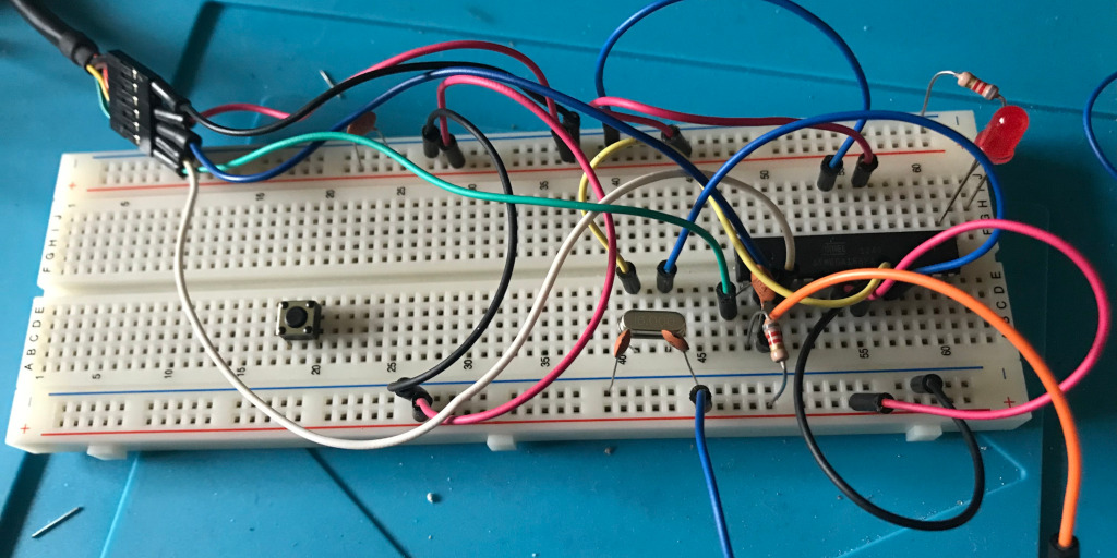
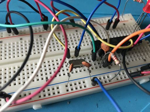
The image to the right is a closer view of the image at the top of this post but to summarise the circuit:
- Power and ground the chip using the VCC and GND outputs from the FTDI cable. Use a 100nF (or higher) capacitor across the power lines.
- Set up the 16MHz crystal with 2x 22pF caps to ground on each pin of the crystal. Note that I moved the crystal in this image along to the left of the chip – the circuit is the same just the location of the components on the breadboard are different.
- FTDI’s TX pin to ATMega’s RX pin.
- FTDI’s RX pin to ATMega’s TX pin.
- FTDI’s RTS pin connects to one side of a 100nF capacitor. The other side of the cap is connected to the ATMega’s Reset pin and a 100kOhm resistor to VCC. In other words, a pull-up resistor to VCC, so that the pin’s natural state is VCC. When the pin is at VCC, it is running its boot loaded code normally, when the pin is pulled below VCC, it is in programming mode, enabling us to upload our compiled HEX to the chip.
Finally you can upload your program from the Arduino IDE to the ATmega. Under the Tools menu you’ll need to select the ATmega168 board, that was set up via the Github page discussed above, and set the other options appropriately (16Mhz clock, 168PA variant, Bootloader YES – mostly just the defaults). Then you can write the code and hit Upload to upload it to the chip.
As you’ll see in the image, in my basic test circuit I used an LED and resistor on PB1 or pin 15. One thing to note is that the pin numbers you’d use in the Arduino library functions are mapped differently than the numbers listed on the microcontroller’s datasheet. Here is a useful image that explains the mapping:
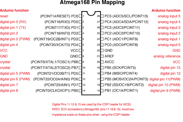
So to access pin 15 on the datasheet, you’d use pin 9 in Arduino IDE. Here is a simple Sketch I used to confirm the set up is working as expected.
int ledPin = 9;
int ledSpeed = 10;
int ledDirection = 1.0;

void setup() {
  // Start serial so that we have access to logs
  Serial.begin(19200);

  // Initialize digital pin as an output.
  pinMode(ledPin, OUTPUT);

  // Log to serial
  Serial.print("\nStart...\n");
}

void loop() {
  digitalWrite(ledPin, HIGH);
  delay(ledSpeed);
  digitalWrite(ledPin, LOW);
  delay(ledSpeed);

  // Modulate led on/off cycle
  ledSpeed = ledSpeed + (ledSpeed * 0.1 * ledDirection);
  if(ledSpeed > 300) {
    ledSpeed = 300;
    ledDirection = -1.0;
  } else if(ledSpeed < 10) {
    ledSpeed = 10;
    ledDirection = 1.0;
  }
}